| < Previous | Up ^ | Next > |

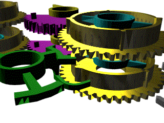
This is a view from the back of the Engine, a close-up of the carry detection mechanism, the green device, that wasn't shown in previous animations.
The figure wheels to the right are the ones that are about to receive the addition, which comes through the magenta sector wheels from the figure wheels to the left. Remember, this image is taken from a point completely opposite the previous images so everything looks reversed.
The carry detector has a curved arm which is almost touching the bottom figure wheel to the right. It also has a couple of teeth on the forked arm right above the curved one. That is the one that adds the carry to the top figure wheel, as will be seen later on. The hammer-like arm in the foreground has some notches on the outer face, which engage with a detention mechanism, not shown in this image (it would block all view to the rest of the mechanism). This détente makes sure the device does not fall into intermediate, undetermined positions.
The carry detector turns loose around the axis, all angular movement is provided externally. It does go up and down with the axle and, at this point, it is shown in the position ready to detect the carry from the bottom wheel, while the forked teeth above are not yet engaged with the top figure wheel.

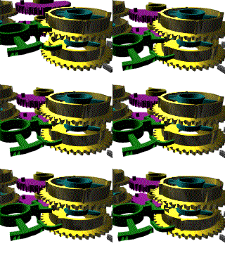
This animation shows the carry detection in action. The carry lever comes down until the curved arm is at a height that matches that of the four external 'decade' teeth around the figure wheel (not the 40 'units' teeth of the main gear). Notice it comes down along the magenta sector wheels. There is a short pause. During this pause, the figure wheel restore arm is about to engage the inner teeth of the figure wheels in the background to the left, as seen in Adding a Digit. When the restore arm hits the inner teeth, the figure wheel in the back starts moving, carrying the sector wheel and the foreground figure wheel. Since the background figure wheels are in different positions (that is, they represent different numbers) they start moving at different points in time.
Soon after the bottom figure wheel in the foreground starts moving, the outer teeth hits the curved detection arm of the carry lever and turns the lever to the 'warned' position.
There is a little gray part at the bottom right corner of the bottom wheel. That is a section of one of several locks that the Engine has, to ensure the wheels remain in place while everything around them is moving. Notice that while the sector wheels come down, the lock remains engaged but it moves aside right before the addition is to happen. The actual lock is not a series of small parts, one for each wheel, but a single bar that runs the full height of the figure wheels, and locks them all at once.
| < Previous | Up ^ | Next > |