
| < Previous | Up ^ | Next > |
The Difference Engine contains 248 figure wheels. Each one of them represents a digit. 31 of them are stacked over a vertical axle to make a complete number of 31 digits. The least significant digit is at the bottom, the highest digit is at the top.
It seems that 31 decimal digits, the equivalent to a 103 bit digital binary processor is too much. Nevertheless, since the whole process is done by successive additions, and each result is based on the previous, the errors tends to accumulate. The following images illustrate the point
|
|
Both images have been produced by the same program. It calculates the function sine over a full turn. The curve in red represents the actual sine curve. The blue and black lines represent the calculation as would have been done by the Difference Engine. The one in the left was done declaring the variables as simple precision (32bit) floating point numbers, while the one on the right was done with double precision variables (64 bits). The calculation proceeds from left to right.
In the image at left, the black lines go astray before reaching a quarter of a turn. One way to solve this is to restart the calculation at another point, such as the blue lines that start at the center of the image and cover another segment.
On the other hand, the image on the right was calculated with variables holding twice the bits (64 bits instead of 32) so the errors, though they exist, are still insignificant for a full turn (the black lines actually do go all the way, a full turn; they can't be seen because they were overlaid by the blue ones).
There is a very delicate balance in between the number of digits, the range you want to calculate the function over and the interval in between points. As a last example, this is what happens when you double the number of intermediate points:

As can be seen, when calculating more points, still with variables of double precision, the black curve also goes astray. In the first two examples, there were 90 individual points, in this example, it was divided into 180 steps. Notice that for a full turn, that is 360 degrees, 180 points means you are having one value per two degrees while the most simple table, a table just one or two pages long, would show values for every minute of arc, with four digit precision.
So much about why so many wheels now, how does a single wheel look like?
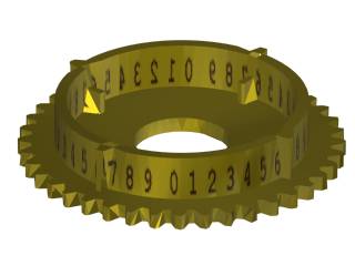 |
Note: this image is not an actual wheel nor it is taken from real drawings or the existing model. Its dimensions are approximate. |
The figure wheel is a gear with 40 teeth. It represents a single digit. The decade is repeated four times just for practical reasons. The Difference Engine No1 had only one decade all around, but the figure wheels were much smaller. To make space for other devices within the wheel, this wheel is larger but it makes smaller movements than otherwise.
The wheel rotates freely around its axle. All movement is done through its teeth, both the ones outside as well as the four ones in the inside. The numerals engraved on the exterior are used to set up the Engine, since its output comes out of the printing mechanism.
The outer nibs, the ones in between numerals 6 and 7, are used to detect a carry from 9 to 0. It would be expected that the nibs would be in between those two numerals but, in fact, it really doesn't matter that the engraved numbers don't match the actual zero of the mechanism. The numerals are placed by the index so the operator can see them, if you moved the index, you would have to move the numerals.
The wheel is not even supported by the axle, it rests on three fingers over which it slides.
| < Previous | Up ^ | Next > |